Which plot corresponds to the step-function expression
y(t) = 5u(t + 3)?
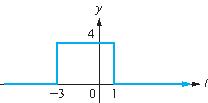
Test 5.2Pulse
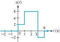
Which expression corresponds to the displayed waveform?
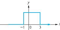
Test 5.3Pulse
Which expression corresponds to the displayed waveform?
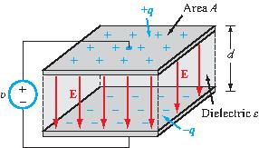
Test 5.4Capacitor
For a parallel-plate capacitor:
Test 5.5Capacitor
For a parallel-plate capacitor:
Test 5.6Capacitor
For a parallel-plate capacitor:
Test 5.7Voltage Division
Voltage division for two in-series capacitors follows the same rule as for:
Test 5.8Voltage Division
Voltage division for two in-series inductors follows the same rule as for:
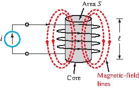
Test 5.9Inductors
The inductance of a solenoid can be increased by increasing its length ℓ.
Test 5.10Inductors
The inductance of a solenoid can be increased by increasing its
cross-section S.
Test 5.11Inductors
The inductance of a solenoid can be increased by
using a ferromagnetic material with large permeability.
Test 5.12Inductors
The inductance of a solenoid can be increased by
using more turns around the cylinder.
Test 5.13Step Function
Which expression corresponds to the displayed waveform?
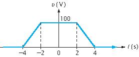
Test 5.14Ramp Waveform
Which expression corresponds to the displayed waveform?
Indicate whether or not the
expression
y(t) = 100r(t + 4) – 100r(t + 2) – 100r(t – 2) + 100r(t – 4)
is a correct representation of the given waveform.
Test 5.15Capacitors under dc Conditions
Determine υ1 under dc conditions.
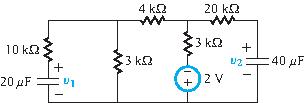
Test 5.16Capacitors under dc Conditions
Determine υ2 under dc conditions.
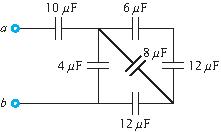
Test 5.17Capacitors
Reduce the circuit into a single equivalent capacitor at terminals
(a,b). All initial voltages are zero at t = 0.
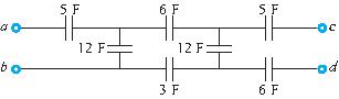
Test 5.18Capacitors
Reduce the circuit into a single equivalent capacitor at terminals
(b,d). All initial voltages are zero at t = 0.
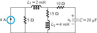
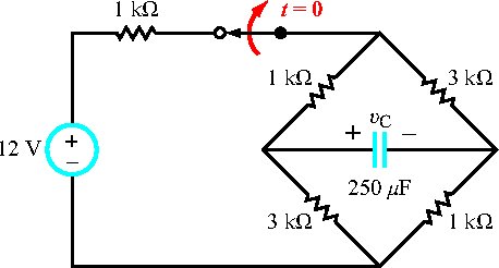
Test 5.19RLC Circuit
Determine υc under dc conditions.
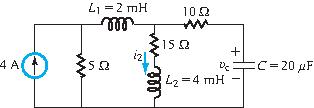
Test 5.20RLC Circuit
Determine i2 under dc conditions.
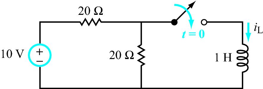
Test 5.21RL Circuit
The current iL(t) for t≥0 is:
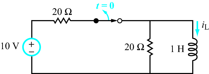
Test 5.22RL Circuit
The current iL(t) for t≥0 is:
Test 5.23RC Circuit
The voltage across the capacitor for t≥0 is:
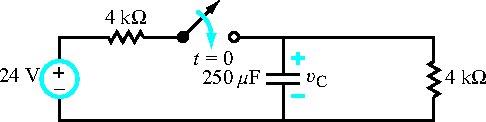
Test 5.24RC Circuit Response
The switch had been open for a long time before it was closed at t=0.
The capacitor's voltage response at t≥0 is (select one answer):
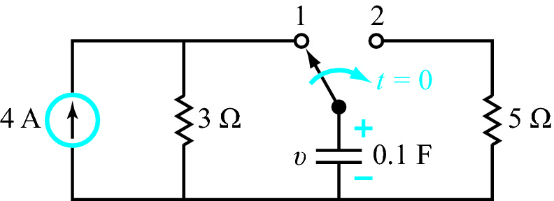
Test 5.25RC Circuit Response
The switch had been in position 1 for a long time before it was moved to position 2 at t=0.
The capacitor's voltage response at t≥0 is (select one answer):
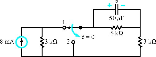
Test 5.26RC Circuit Response
The switch had been closed for al ong time before it was opened at t=0.
The capacitor's voltage response at t≥0 is (select one answer):
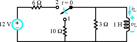
Test 5.27RL Circuit Response
The switch had been in position 1 for a long time before it was moved to poistion 2 at t=0.
The inductor's current response at t≥0 is (select one answer):
Test 5.28RL Circuit Response
The switch had been in position 1 for a long time before it was moved to position 2 at t=0.
The inductor's current response at t≥0 is (select one answer):
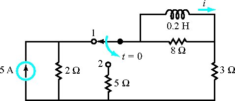
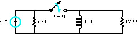
Test 5.29RL Circuit Response
The switch had been open for a long time before it was closed at t=0.
The inductor's current response at t≥0 is (select one answer):
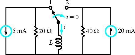
Test 5.30RL Circuit Response
The switch had been in position 1 for a long time before it was moved to position 2 at t=0.
If L=0.8 H, the inductor's current response at t≥0 is (select one answer):
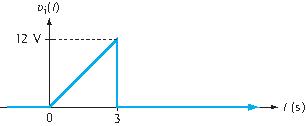
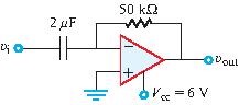
Test 5.31RC Op-Amp Circuit
The input voltage waveform shown in (a) is applied to the circuit shown in (b).
(a)(b)
Which of the following is the correct output voltage waveform?