Complex power S contains two components, which are
Test 8.2Complex Power
For a purely capacitive load, the average absorbed power is
Test 8.3Power Factor
For a purely resistive load, the power factor is
Test 8.4Power Factor
For a purely capacitive load, the power factor is
Test 8.5Maximum Power Transfer
A source circuit with impedance Zs = Rs +
jXs is connected to a load ZL =
RL + jXL. To effect maximum transfer of power
to the load, the load should be designed such that
Test 8.6Average Value
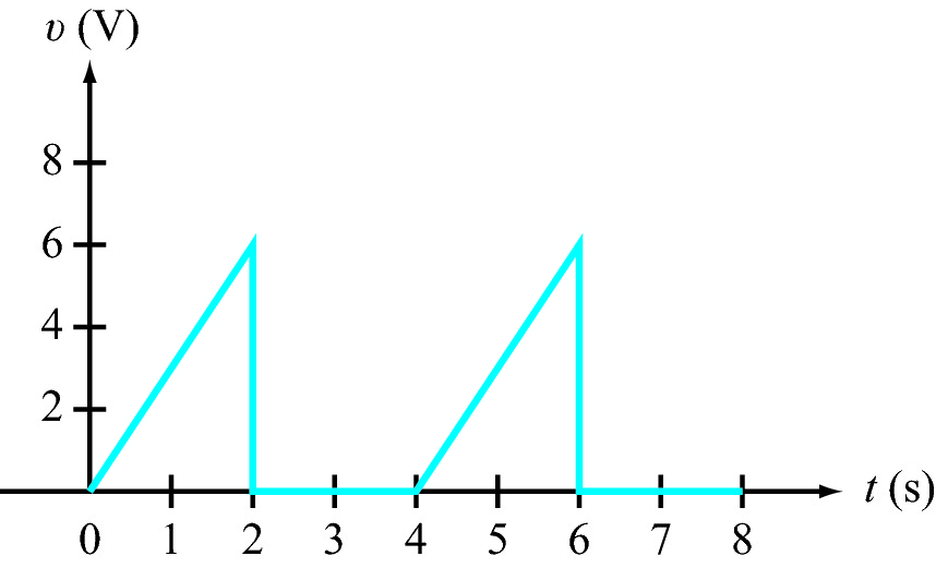
What is the average vale of ν(t)?
Test 8.7RMS Value
What is the rms value of ν(t)?
Test 8.8Power Factor
The voltage and current at the input to a load circuit are given by
υ(t) = 100 cos(377t - 30°) V,
i(t) = 5 cos(377t + 30°) A.
The load power factor is
Test 8.9Average Power
The voltage and current at the input to a load circuit are given by
Vrms = 100∠75° V,
Irms = 2∠15° A.
The average absorbed power is
Test 8.10Average Power
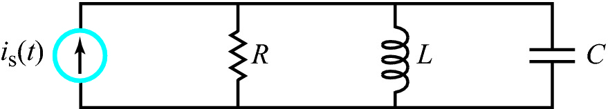
In the circuit,
is(t) = 0.2 sin 105t A,
R = 20 Ω, L = 0.05 mH, and C = 2 μF.
Determine the average power dissipated in R.
Test 8.11Power Factor
In the circuit,
is(t) = 0.2 sin 105t A,
R = 20 Ω, L = 0.05 mH, and C = 2 μF.
The power factor of the source is
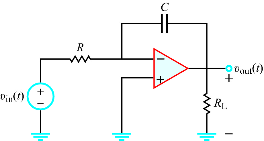
Test 8.12Op-Amp Circuit
In the circuit,
υin(t) = 10 cos(1000t) V,
R = 10 kΩ, RL = 1 kΩ, and C = 1 μF.
The average power dissipated in RL is:
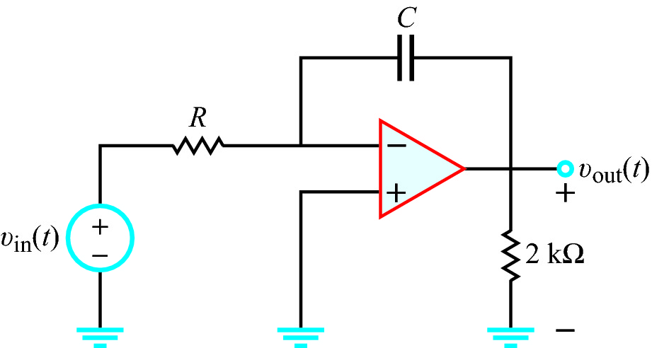
Test 8.13Op-Amp Circuit
In the circuit,
υin(t) = 10 cos(1000t) V,
R = 10 kΩ, RL = 2 kΩ, and C = 1 μF.
The average power dissipated in RL is:
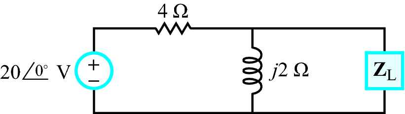
Test 8.14Maximum Power Transfer
Choose the load ZL so that the power dissipated in
it is a maximum.
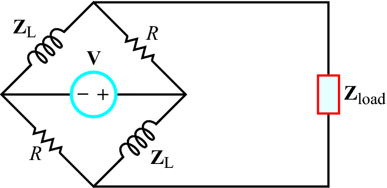
Test 8.15Maximum Power Transfer
In the phasor-domain circuit, R = 2 kΩ and ZL=
j2 kΩ. Choose the load impedance so that the power dissipated
in it is a maximum.